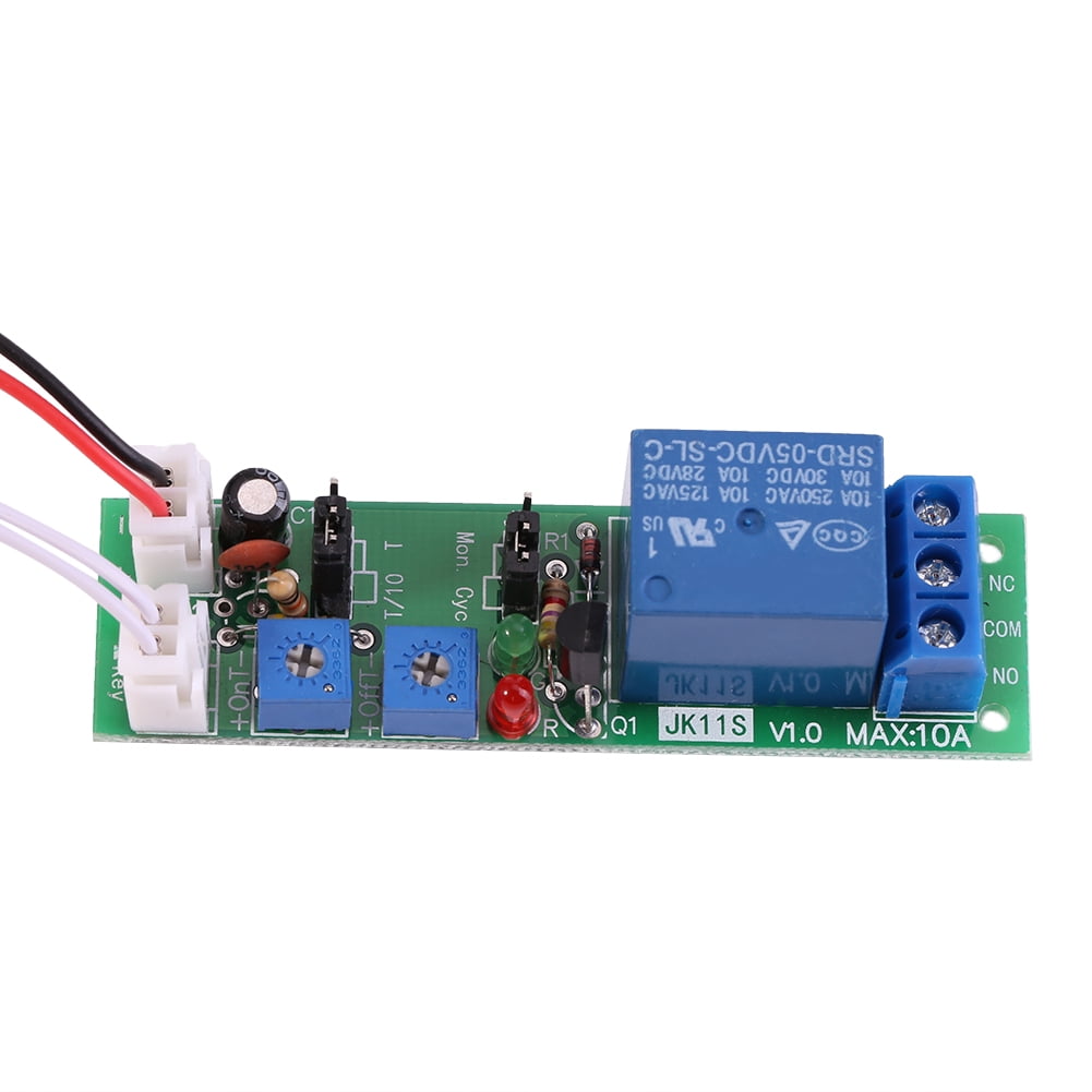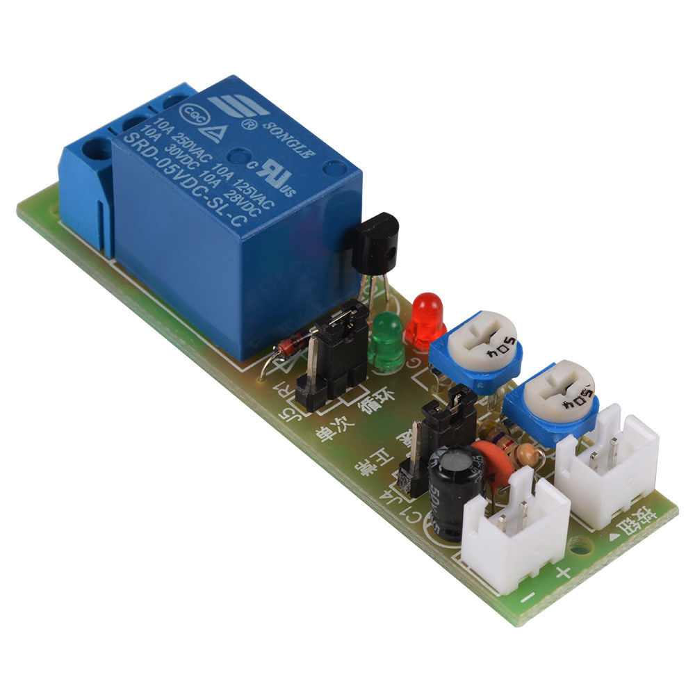


Now, remove the LED and insert the optotriac MOC3041, triac BT139 and associated components. If LED glows after a time delay, your circuit is working well. If voltage pulses are available at pin 3 of IC NE555, check 4017B and its associated components. If LED does not glow, check voltage at pin 3 of NE555 with multimeter.
#24V POWER ON TIME DELAY CIRCUIT DOWNLOAD#
5: Components layout of the PCB Download PCB and Component Layout PDFs: click hereįor initial testing, remove IC3 from the circuit and connect an LED across pins 1 and 2 of MOC3041. 4: PCB layout for the power-on delay timer Fig. After assembling the circuit, connect the 230V, 50Hz AC supply across CON1. Construction and testingĪ PCB layout for the power-on delay timer is shown in Fig. To improve the life of triac, the spike arrester circuit built around resistor R9, metal oxide varistor MOV1 and capacitor C7 is used. This triggers the main triac BT139 and the AC supply for the load becomes available across connector CON2. High state at Q9 makes MOC3041 to conduct. The current high output states of 4017B remain high till the power is off. This stops the counting process in 4017B. When Q9 goes high with tenth pulse, CLK EN also goes high. Each output of 4017B goes high one by one after each clock pulse. You can change the delay time (0.1 to 1-sec) of this circuit by varying VR1.ĭuring power-on, clock enable pin 13 (CLK EN) and pin 11 (Q9) of 4017B are in low states. Resistor R2, capacitor C5 and preset VR1 are timing components for NE555 IC. Optotriac has the advantage of triggering 230V AC power by itself and providing circuit isolation.ĭC power for this circuit is derived from step-down transformer X1, bridge rectifier BR1 and capacitors C3 and C4. The triac is triggered by optotriac MOC3041 (IC3). The optimum load will be 220V×9.6A=2112 watts. The maximum 16-ampere current means we can have 60 per cent as optimum current, that is, up to 9.6 amperes (or 16×0.6=9.6 amperes). The output is built around triac BT139, which can switch up to 16-ampere AC load. Output pin 11 (Q9) of 4017B goes high at 10th pulse received from NE555. As a result, 4017B gets breezed and its ten outputs (Q0 through Q9) become high sequentially. The output pulses from NE555 are fed to clock input pin 14 of 4017B. When the main power is switched on, 4017B starts counting the pulses received from NE555. VR1 preset is used to vary the timings from 0.1-sec to 1-sec pulse in NE555 IC. NE555 IC is used as a bistable oscillator. This helps you find a break in your circuit board, which would be necessary for fixing if it were broken or defective.Timing accuracy is achieved by using decade counter 4017B. You can do this by using an electric probe and multimeter to test the device’s internal connections. When working with time delay relays, it’s essential to test them correctly to work correctly. You can test each connection on both sides until you find where it breaks to determine what needs fixing! This method works just as well with regular relays, too – even though they don’t have coils like these do, their internal switches still have to be connected properly for the device to work. You will hear an audible sound if there’s no breakage within the device itself when doing so. You can also use a multimeter to check for continuity between each side of the “on” coil and ground (which should be represented by two probes touching at once). If it does not show up, then this means that your time delay relay is either defective or has a broken wire in its circuit board somewhere. This shows up as a temporary reverse flow of electricity when you move your probe from one coil to the other. When doing this correctly, you will see a back EMF when electricity flows through wires and other conducting materials like metals. You’ll want to connect these probes where each end should go into either side of the “on” coil on the time delay relay (the larger probe should be connected in between). Then get an electric probe or any electrical testing tool that has two metal ends (one small & one large) so that both can touch at once inside of your circuit board. First of all, make sure the device is turned off and unplugged from its power source. If you’re trying to test a time delay relay, there’s an easy way to do it.


 0 kommentar(er)
